Lab 4 - Open Loop Control
Parts and Files Needed:
- 1 x SparkFun RedBoard Artemis Nano
- 1 x USB A-to-C cable
- 1 x Li-Ion 3.7V 400 or 500mAh battery
- 1 x Sparkfun Qwiic motor driver
- 1 x R/C stunt car and NiCad battery
- 1 x Qwiic connector
- 1 x Small screwdriver
- 1 x Wirecutter
Manual Open Loop Control of the RC Car (4a)
1. Communicating with the Motor Driver
I used the code from File->Examples->Wire->Example1_wire and checked the I2C address of the motor driver. The I2C address was found to be 0x5D.

2. Taking apart the RC Car
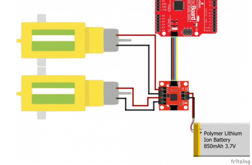
I first unscrewed and removed the bumper of the RC car. I took out the battery and cut the power wires and motor wires from the PCB. I then followed the hookup guide and connected the wires to the motor driver:

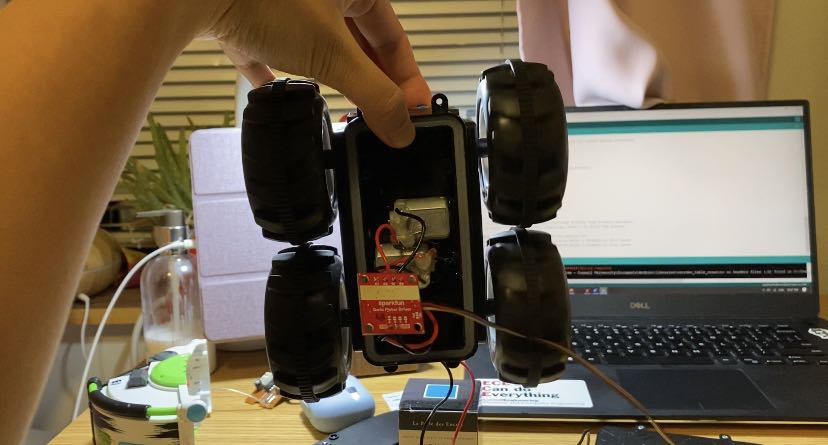
I had to be very careful with the motor driver wires because they could be easily pulled off. I also had to make sure that the red wire from the battery cable is connected to VIN on the motor driver. Here’s a picture of the car during testing, with everything hooked up:

3. Testing the Car
In order to test the car with the new motor driver, I downloaded the SCMD library from Arduino. In the MotorTest example, I first changed the I2C address to 0x5D:
myMotorDriver.settings.I2CAddress = 0x5D; //config address to motor driver address
Originally, the code inside the loop goes through all 34 motors and step through them. Since we only have two motors, I simply set motor 0 and motor 1. The following code drives the robot straight on both motors at 60.
    myMotorDriver.setDrive( 1, 1, 60); //Drive motor 1 forward at 60
    myMotorDriver.setDrive( 0, 0, 60); //Drive motor 0 forward at 60
In order to figure out the lower limit for which each motor still turns, I tested them at 40, 30, 25, and 20. At 40, both motors were able to turn without a starting push. At 30, both motors can turn, but they need a little push manually. At 25, motor 1 can turn with a little push but not motor 0. At 20, both motors weren’t able to turn. A demonstration video is shown below:
I also tested the robot following a straight line in both fast and slow speeds. For fast speed, I set both the left and right motors to 180. For slow speed, I set motor 1 to 50 and motor 2 to 60 for calibration. The robot started with the tapemark in its center, and it’s able to land with part of the body overlapping the tape, as demonstrated below:
4. Robot Assembly
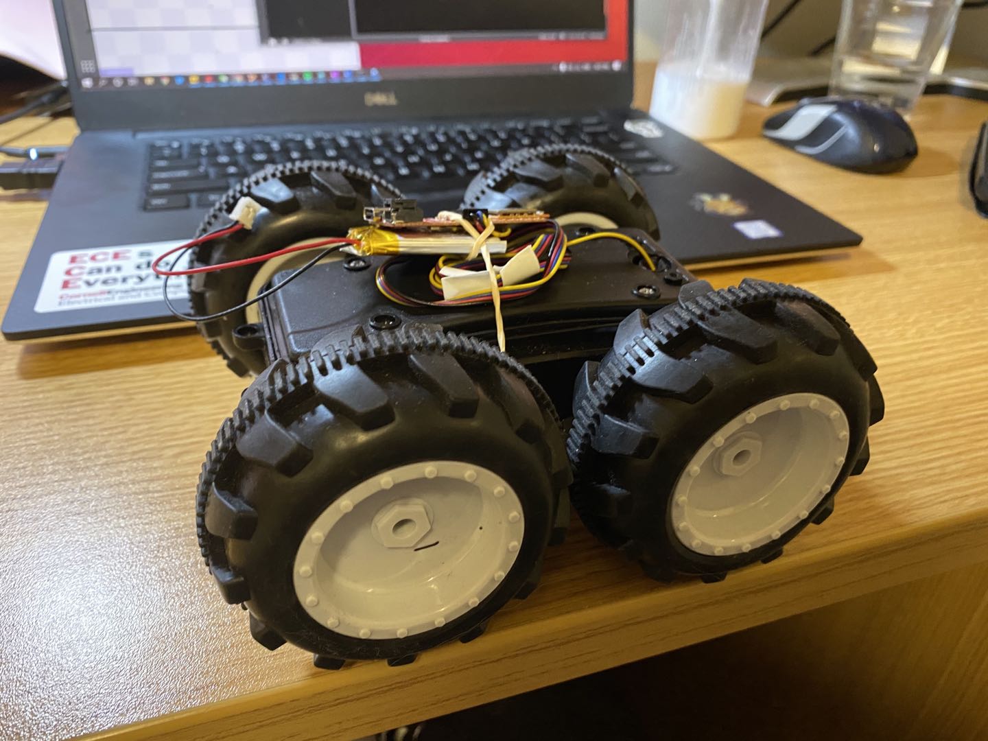
After testing the motor driver, I assembled the robot by putting the motor driver inside and routing the connector to the outside of chassis through the hole for the old start buttom. I used a rubber band because the tape wasn’t strong enough to hold them down.

Here’s a video of the robot doing some turns. Since the floor surface wasn’t super flat in my apartment, the turns weren’t exactly the same. One thing I realized was that the turns can only happen on my floor surface/carpet when the speed of the motors is above ~180 due to the traction of the wheels. If the speed is too low, the robot gets stuck instead of turning. It helps if I make the robot stop before it turns and if I make it turn using both wheels.
    myMotorDriver.setDrive( 1, 1, 60); //motor 1 drives straight
    myMotorDriver.setDrive( 0, 0, 60); //motor 0 drives straight
    delay(1000);
    myMotorDriver.setDrive( 1, 1, 0); //Stop
    myMotorDriver.setDrive( 0, 0, 0); //Stop
    delay(500);
    //turn left
    myMotorDriver.setDrive( 1, 1, 180); //motor 1 turns
    myMotorDriver.setDrive( 0, 1, 180); //motor 0 turns the other direction
    delay(750);
    myMotorDriver.setDrive( 1, 1, 60);
    myMotorDriver.setDrive( 0, 0, 60);
    delay(1000);
    myMotorDriver.setDrive( 1, 1, 0); //Stop
    myMotorDriver.setDrive( 0, 0, 0); //Stop
    delay(500);
    //turn right
    myMotorDriver.setDrive( 1, 0, 180); //motor 1 turns the other direction
    myMotorDriver.setDrive( 0, 0, 180); //motor 0 turns
    delay(750);
Open Loop Control Of Virtual Robot (4b)
Need:
- Lab4 codebase
- Jupyter Notebook
5. Setup
The part of the lab needs the Jupyter notebook and the lab4 codebase downloaded via terminal. After following the instructions on the website, I changed the kernel to Python 3(it was set to Python 2 before).
6. Rectangular Loop
In order to make the robot go in a rectangular loop, I needed to set the linear velocity (for straight lines) and angular velocity (for turns). After some googling, I realized that v = r X w, where v is the linear velocity and w is the angular velocity per unit time. Therefore, v/w would be the radius that the robot can turn. Since we want a fairly tight turn, I set the ratio of v/w to be small. After a couple trials, I decided that v=0.1 and w=20 would be a good turn radius.
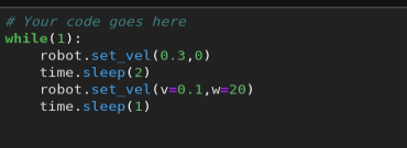
To make the robot go straight, I set the linear velocity to 0.3 and the angular velocity to 0. My code is below:

Here’s the video of the virtual robot going in a rectangular loop: